BRAN SANDS
Commercial | Redcar
Commercial | Redcar
In July 2024, NTB Survey was commissioned by Betts Associates to carry out a comprehensive topographical survey at Bran Sands Water Treatment Works near Redcar, on behalf of Northumbrian Water.
The primary purpose of the survey was to support a site-wide bund containment assessment, making sure that the facility complied with current environmental containment standards and informing them of any future upgrades to bunding infrastructure.
The survey formed a critical part of Northumbrian Water’s broader asset management and planning strategy. A high level of detail was required to support design and compliance decisions. Particularly around the layout and interaction of structural and drainage features.
The brief specified that final deliverables should be presented in both 2D and 3D CAD formats, with an accurate and comprehensive depiction of all key elements across the survey area.
The survey covered an area of approximately 70 metres by 50 metres. Within that space there was two 7m diameter TAS sludge tanks, outbuildings, extensive bund structures and a network of complex above-ground pipework.
The site also included numerous surface-level drainage features, manholes and changing ground materials across operational zones.
The site’s layout required a three-dimensional understanding of spatial relationships, especially between elevated pipe runs and surrounding structures. This meant that a 3D topographical output was essential for both design review and future planning.
Betts Associates provided a detailed specification which required full capture of:
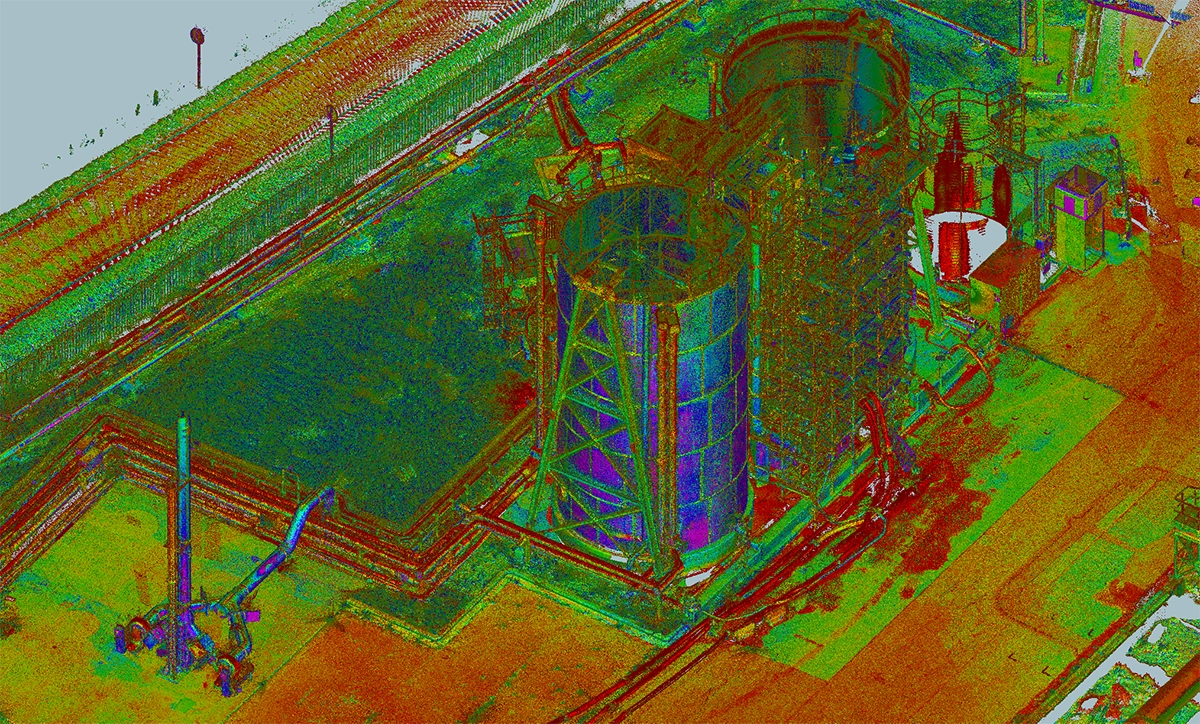
Profiles of tanks, bunds and outbuildings
Top and bottom levels of bunds and slopes
Types of surface materials and their join lines or interfaces
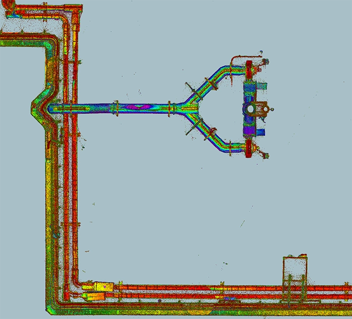
All visible pipework and supports, including above-ground and raised sections
Drainage infrastructure, including positions and types of manholes
Pipe sizes, invert levels and direction of flow where chambers could be accessed
The best equipment for the job was the Leica laser scanner which allowed us to take a full 3D scan of the area. It’s accuracy was crucial for recording the detailed pipework arrangements, vertical tank walls, and bund contours. The scanning process resulted in a dense pointcloud dataset, which was the basis for all subsequent CAD work.
Before scanning began, we established a survey control network across the site to allow more control and ensure positional accuracy throughout the scan registration.
Multiple scan positions were set up around the site to capture all surfaces and structures from various angles. This allowed us to register the scans into a single, unified pointcloud that included full detail from ground level up to the highest pipe runs and tank profiles.
Manholes were opened and inspected where safe to do so, allowing us to record invert levels, pipe diameters and direction of flow. Where access was restricted or unsafe, we made cautious inferences based on surface features and drainage fall, with any assumptions clearly annotated in the drawings.
Once the pointcloud was complete, we used it to create a detailed 3D topographical drawing in survey processing software & computer aided design (CAD). This involved interpreting and tracing all required features: tank outlines, bund edges and levels, outbuilding footprints and critically, the pipework that crossed above/between structures. We paid particular attention to surface join lines, capturing the boundaries between concrete, tarmac and other materials, which were important for drainage and construction detailing.
This approach using laser scanning provided a safer and more comprehensive method of measurement compared to conventional total station-only techniques. It also allowed us to return to the dataset in the office and re-check any part of the site in 3D, avoiding the need for time consuming revisits.
A number of technical and environmental challenges arose during the course of this survey
The site involved complex and overlapping runs at varying heights and angles. In several locations the pipework passed close to structures or dipped below gantries, requiring extra scan coverage and careful interpretation in CAD to ensure nothing was missed or misrepresented.
While we were able to open the majority safely, a few chambers were either seized or located within operational zones where lifting covers was not permitted due to health and safety restrictions. In those cases, we relied on visible clues and surrounding infrastructure to suggest the direction of flow and approximate invert levels.
This required continuous coordination with Northumbrian Water’s on-site team to ensure that the work caused no disruption to operations, while also adhering to strict health and safety protocols. We had to flexible and adhere to a careful working pattern. The tanks themselves were operational, so we kept a safe distance and used long-range scanning when required.
The final deliverables consisted of a fully detailed 3D topographical drawing and a ‘flattened’ 2D drawing, both issued in DWG format
Fully annotated levels and contours
Accurate representation of tanks, bunds and outbuildings
Pipework shown with correct heights and alignments
Drainage infrastructure with cover levels, types and invert data where available
Surface materials and joint boundaries clearly defined
Feedback from Betts Associates was very positive, with no amendments requested. The outputs were passed to Northumbrian Water’s engineering and asset planning teams for use in current and future infrastructure reviews.
The 3D model in particular offered valuable clarity in terms of pipe clearance, bund volume capacity and drainage routing. It allowed engineers to make informed decisions for design and compliance.
The survey outputs provided Betts Associates and Northumbrian Water with the robust foundation they needed to assess containment capacity, plan for improvements and ensure compliance with bunding and drainage regulations.